The IR sensor is (in my best-case scenario) only detecting a single hole per disc rotation. At 12.5Hz, in other words.
I'm thinking I can use a second timer running at a very casual rate to do an ADC read of the pin to which the IR RX is connected. Even if we stick with 31/32 holes, it's still going to be very pedestrian in terms of timer and resource usage. I basically just copy the audio-reading timer and process some level as "sync hole" else "no hole".
The synchrnoisation will consist of a PLL or perhaps just some simple if/else code that compares the sync from the audio timer code with the sync from the IR timer code. A quick search doesn't show much on PLL with Arduino so I'll get back to that. The actual motor control could be done inside the IR timer - do a PWM adjustment based on the synch pulse comparison right then and there.
And of course the PWM is just a variable giving the PWM "speed" for the motor at any given time, and static (and constantly applied) until the next sync "decision".
Narrow-Bandwidth Television Association
Forum for discussion of television and imaging using mechanical, radio, and early electronic systems.
IR - Detecting Speed of the Disc
Moderators: Dave Moll, Andrew Davie, Steve Anderson
22 posts
• Page 1 of 2 • 1, 2
IR - Detecting Speed of the Disc
![]() by Andrew Davie » Thu Mar 02, 2017 11:27 pm
by Andrew Davie » Thu Mar 02, 2017 11:27 pm
-

Andrew Davie - "Gomez!", "Oh Morticia."
- Posts: 1590
- Joined: Wed Jan 24, 2007 4:42 pm
- Location: Queensland, Australia
-
Andrew Davie - "Gomez!", "Oh Morticia."
- Posts: 1590
- Joined: Wed Jan 24, 2007 4:42 pm
- Location: Queensland, Australia
Re: IR - Detecting Speed of the Disc
![]() by Andrew Davie » Sat Mar 04, 2017 1:37 am
by Andrew Davie » Sat Mar 04, 2017 1:37 am
Going to separate the PLL out into a different topic.
The IR sensor pair can be handled using a Schmitt Trigger. That's a circuit that takes a varying analog signal and converts it to a square wave with the transition points at defined voltages, with a deadband between them. Can be used for anything from debouncing key presses to... IR sensor on/off detection. I'm looking at a schmitt trigger for the IR so that a digital input can be used on the arduino and not take-up or waste an ADC resource.
My current thinking is to find an IC that does this for me, and given the IR signal can be up to 10V or so (I recall) then this looks like a possible...
https://www.jaycar.com.au/medias/sys_master/images/8936372633630/ZC4914-dataSheetMain.pdf
-
Andrew Davie - "Gomez!", "Oh Morticia."
- Posts: 1590
- Joined: Wed Jan 24, 2007 4:42 pm
- Location: Queensland, Australia
Re: IR - Detecting Speed of the Disc
![]() by Andrew Davie » Mon Mar 06, 2017 11:03 pm
by Andrew Davie » Mon Mar 06, 2017 11:03 pm
Well, it seems that the Arduino has an on-board "comparator"
From the interesting Girino - Fast Arduino Oscilloscope documentation I see that...
Now the Arduino Micro I'm using has a different processor, but the general process is the same, I'm sure. Essentially, the IR detection signal is on an analog pin, and we set some reference level above which means "I see a hole" and an interrupt is triggered and we handle that. Pretty much a boolean flag, which is our "synch hole". Going with just one hole per frame at this stage, so we have frame synch capability - but fallback is to have the old standard 31/32.
But for now, the goal is to get the IR sensors working as a stand-alone (power 'em (from the arduino?)) and detect 'em with a comparator, and that's all we need to do for that part.
The next part will be to use the sync separated from the signal (not yet tackled!) and the boolean "synch hole" flag to run a PLL (phase-locked loop) controlling the duty cycle of the motor PWM channel. And then we'll have synch and a steady frame.
So, first... let's investigate the comparator interrupt and get the IR sensors powered. ...
From the interesting Girino - Fast Arduino Oscilloscope documentation I see that...
The ATMega328P has an Analog Comparator that has an interrupt associated that is activated when a signal surpasses a reference voltage. First of all you must define the function that will be exectuted:
ISR(ANALOG_COMP_vect)
{
counter++;
}
This is really simple, the instruction ISR() is a macro that tells the compiler that the following function is an Interrupt Service Routine. While ANALOG_COMP_vect is called Interrupt Vector and it tells the compiler which interrupt is associated to that routine. In this case it is the Analog Comparator Interrupt. So everytime that the comparator sees a signal bigger than a reference it tells the microcontroller to execute that code, id est in this case to increment that variable.
The next step is to enable the interrupt associated. To enable it we must set the ACIE (Analog Comparator Interrupt Enable) bit of the ACSR (Analog Comparator Setting Register) register:
sbi(ACSR,ACIE);
In the following site we can see the list of all Interrupt Vectors:
http://www.nongnu.org/avr-libc/user-man ... rupts.html
Now the Arduino Micro I'm using has a different processor, but the general process is the same, I'm sure. Essentially, the IR detection signal is on an analog pin, and we set some reference level above which means "I see a hole" and an interrupt is triggered and we handle that. Pretty much a boolean flag, which is our "synch hole". Going with just one hole per frame at this stage, so we have frame synch capability - but fallback is to have the old standard 31/32.
But for now, the goal is to get the IR sensors working as a stand-alone (power 'em (from the arduino?)) and detect 'em with a comparator, and that's all we need to do for that part.
The next part will be to use the sync separated from the signal (not yet tackled!) and the boolean "synch hole" flag to run a PLL (phase-locked loop) controlling the duty cycle of the motor PWM channel. And then we'll have synch and a steady frame.
So, first... let's investigate the comparator interrupt and get the IR sensors powered. ...
-
Andrew Davie - "Gomez!", "Oh Morticia."
- Posts: 1590
- Joined: Wed Jan 24, 2007 4:42 pm
- Location: Queensland, Australia
Re: IR - Detecting Speed of the Disc
![]() by Andrew Davie » Thu Mar 09, 2017 12:00 am
by Andrew Davie » Thu Mar 09, 2017 12:00 am
Time to start thinking about how to drive/sense the IR pair.
Here's what I'm using...
5mm Infrared Transmitting LED
Infrared Phototransistor
I have to re-learn all about LEDs and how an IR pair works. In my first build, I kind of just wired up the circuit and plugged things in to the correct places, and it worked. This time I'm going to be driving the pair from the Arduino so I need to know voltage, current requirements, etc. I recall that LEDs are current-driven devices and there was a voltage drop across the LED, and you used a resistor to limit the current and you could chain multiple LEDs and if the voltage was sufficient to cross all LEDs then you got light
So I'm thinking the transmitter will have a minimum voltage - we're able to supply 5V from the Arduino so that can power the transmitter directly. The receiver is going to be analog, and we'll get into how to detect that later on. For now, let's get that transmitter lit up.
Going to use the mobile phone camera to detect when the LED is lighting up (because it's infrared, and I know the camera sees those wavelengths and conveniently converts down to a visible wavelength when displayed on its screen). I think what's required is a simple current-limiting resistor between the pin and the IR diode and sufficient voltage and it should light up. The long lead is positive, so I guess I'll just give that a quick test and see how that goes.
"Be sure to connect your LED correctly! The long leg is positive and connects to the resistor, then to the Arduino’s output pin. The short leg is negative and is connected to ground (GND)."
So, data sheet, what's the current requirements for the xmit IR diode? Mmh... that would be forward current...? Says 50 mA - 200 mA. I see it says "duty 1/10 @ 1KHz". OK I think by "continuous forward current 50mA" I think it's saying that IF you are going to power it constantly then 50mA is the maximum. However, if you use 1/10 duty cycle at 1KHz then you can send 200mA. I'm not going to worry about that too much - just have to keep the current under 40mA for the Arduino pin.
So, 5V from the Arduino 5V pin, 40 mA - that's 5/0.04 ohms resistor = 125 ohms. << WRONG! Need to take account of the voltage drop across the LED.
Let's be conservative and go with 150 or thereabouts.
OK, wiring is 5V pin on the Arduino connects to 150 ohm resistor, connects to the long lead of the IR transmit LED, then short pin back to the GND pin on the Arduino. And it's lit up. How easy was that! The voltage drop of the LED should be counted when calculating the resistor. Looking at the data sheet, that's probably the forward current vs. forward voltage graph and I see we're looking at about 1.4 V. This would make the voltage "across" the resistor (5-1.4) = 3.6V and then allowing 30mA just to be conservative we get 3.6/0.03 = 120 ohm resistor. I tested with a 150 ohm, and that would give 24 mA which is just fine. Edit: 20 mA is recommended!
So, 3.6/0.02 = 180 ohms - so next time I do a test I'll use that.
The Arduino Micro has its own limits; per I/O pin it's just 20 mA, with 10 mA recommended. For the 5V I've been unable to find the recommended or maximum current.
Here's what I'm using...
5mm Infrared Transmitting LED
 ZD1945-dataSheetMain.pdf
- (203.6 KiB) Downloaded 511 times
Infrared Phototransistor
- ZD1950-dataSheetMain.pdf
- (71.25 KiB) Downloaded 505 times
I have to re-learn all about LEDs and how an IR pair works. In my first build, I kind of just wired up the circuit and plugged things in to the correct places, and it worked. This time I'm going to be driving the pair from the Arduino so I need to know voltage, current requirements, etc. I recall that LEDs are current-driven devices and there was a voltage drop across the LED, and you used a resistor to limit the current and you could chain multiple LEDs and if the voltage was sufficient to cross all LEDs then you got light
So I'm thinking the transmitter will have a minimum voltage - we're able to supply 5V from the Arduino so that can power the transmitter directly. The receiver is going to be analog, and we'll get into how to detect that later on. For now, let's get that transmitter lit up.
Going to use the mobile phone camera to detect when the LED is lighting up (because it's infrared, and I know the camera sees those wavelengths and conveniently converts down to a visible wavelength when displayed on its screen). I think what's required is a simple current-limiting resistor between the pin and the IR diode and sufficient voltage and it should light up. The long lead is positive, so I guess I'll just give that a quick test and see how that goes.
"Be sure to connect your LED correctly! The long leg is positive and connects to the resistor, then to the Arduino’s output pin. The short leg is negative and is connected to ground (GND)."
So, data sheet, what's the current requirements for the xmit IR diode? Mmh... that would be forward current...? Says 50 mA - 200 mA. I see it says "duty 1/10 @ 1KHz". OK I think by "continuous forward current 50mA" I think it's saying that IF you are going to power it constantly then 50mA is the maximum. However, if you use 1/10 duty cycle at 1KHz then you can send 200mA. I'm not going to worry about that too much - just have to keep the current under 40mA for the Arduino pin.
So, 5V from the Arduino 5V pin, 40 mA - that's 5/0.04 ohms resistor = 125 ohms. << WRONG! Need to take account of the voltage drop across the LED.
Let's be conservative and go with 150 or thereabouts.
- LED.jpg (290.42 KiB) Viewed 13616 times
OK, wiring is 5V pin on the Arduino connects to 150 ohm resistor, connects to the long lead of the IR transmit LED, then short pin back to the GND pin on the Arduino. And it's lit up. How easy was that! The voltage drop of the LED should be counted when calculating the resistor. Looking at the data sheet, that's probably the forward current vs. forward voltage graph and I see we're looking at about 1.4 V. This would make the voltage "across" the resistor (5-1.4) = 3.6V and then allowing 30mA just to be conservative we get 3.6/0.03 = 120 ohm resistor. I tested with a 150 ohm, and that would give 24 mA which is just fine. Edit: 20 mA is recommended!
So, 3.6/0.02 = 180 ohms - so next time I do a test I'll use that.
The Arduino Micro has its own limits; per I/O pin it's just 20 mA, with 10 mA recommended. For the 5V I've been unable to find the recommended or maximum current.
-
Andrew Davie - "Gomez!", "Oh Morticia."
- Posts: 1590
- Joined: Wed Jan 24, 2007 4:42 pm
- Location: Queensland, Australia
Re: IR - Detecting Speed of the Disc
![]() by Andrew Davie » Thu Mar 09, 2017 12:11 am
by Andrew Davie » Thu Mar 09, 2017 12:11 am
It will be a good idea to move the IR transmitter from the 5V pin to a digital pin so that we can turn the diode off when it is not required.
So, will test that out soon, too!
So, will test that out soon, too!
-
Andrew Davie - "Gomez!", "Oh Morticia."
- Posts: 1590
- Joined: Wed Jan 24, 2007 4:42 pm
- Location: Queensland, Australia
Re: IR - Detecting Speed of the Disc
![]() by Klaas Robers » Thu Mar 09, 2017 2:11 am
by Klaas Robers » Thu Mar 09, 2017 2:11 am
The easiest way is to connect the diode with a resistor in series between +5V and ground. There is no real need to switch thee diode off, so let it be on as long as the NBTV monitor is in use.
The resistor is 3.5 volt / 0.020 (indeed 20 mA) = 175 ohm, so 180 ohm.
The resistor is 3.5 volt / 0.020 (indeed 20 mA) = 175 ohm, so 180 ohm.
-

Klaas Robers - "Gomez!", "Oh Morticia."
- Posts: 1656
- Joined: Wed Jan 24, 2007 8:42 pm
- Location: Valkenswaard, the Netherlands
Re: IR - Detecting Speed of the Disc
![]() by Andrew Davie » Thu Mar 09, 2017 6:07 pm
by Andrew Davie » Thu Mar 09, 2017 6:07 pm
My first attempt at wiring up the IR detector and seeing if I could get a signal... actually worked!
For the photodiode, I connected the cathode (-) to the same 5V supplying the IR transmitter. I put a resistor (1.5K) between the anode and ground. I connected the anode to the analog input A0 on the Ardino. Essentially as I understand it, when the diode is conducting (detecting IR) then the current flows to ground through the resistor. When the diode is not conducting, then the pathway is directly to the A0 analog input pin.
I put my oscilloscope across the pins of the photodiode, effectively measuring the voltage to the analog pin. I see about a 4.5V difference between when the diodes are pointing at each other with no obstruction (nominally, "0V") and when there is a barrier between them (4.5V). So, I think it's working!
Time to do the following...
* wire up my 3D printed IR sensor mount with some diodes installed, and place it around the Nipkow disc
* write a small arduino test program to initialise the A0 pin for input and read the values in a loop just to show that it works on the Arduino side
* perhaps start to think about how the comparator works..
- irpair.jpg (310.97 KiB) Viewed 13599 times
For the photodiode, I connected the cathode (-) to the same 5V supplying the IR transmitter. I put a resistor (1.5K) between the anode and ground. I connected the anode to the analog input A0 on the Ardino. Essentially as I understand it, when the diode is conducting (detecting IR) then the current flows to ground through the resistor. When the diode is not conducting, then the pathway is directly to the A0 analog input pin.
I put my oscilloscope across the pins of the photodiode, effectively measuring the voltage to the analog pin. I see about a 4.5V difference between when the diodes are pointing at each other with no obstruction (nominally, "0V") and when there is a barrier between them (4.5V). So, I think it's working!
Time to do the following...
* wire up my 3D printed IR sensor mount with some diodes installed, and place it around the Nipkow disc
* write a small arduino test program to initialise the A0 pin for input and read the values in a loop just to show that it works on the Arduino side
* perhaps start to think about how the comparator works..
-
Andrew Davie - "Gomez!", "Oh Morticia."
- Posts: 1590
- Joined: Wed Jan 24, 2007 4:42 pm
- Location: Queensland, Australia
Re: IR - Detecting Speed of the Disc
![]() by Andrew Davie » Thu Mar 09, 2017 6:28 pm
by Andrew Davie » Thu Mar 09, 2017 6:28 pm
I think I need to learn the correct symbols for things, and get some circuit drawing software. Until then, back of the envelope will have to do. This shows how I think I have everything connected at the moment.
- ircircuit.jpg (177.83 KiB) Viewed 13599 times
-
Andrew Davie - "Gomez!", "Oh Morticia."
- Posts: 1590
- Joined: Wed Jan 24, 2007 4:42 pm
- Location: Queensland, Australia
Re: IR - Detecting Speed of the Disc
![]() by Klaas Robers » Thu Mar 09, 2017 8:15 pm
by Klaas Robers » Thu Mar 09, 2017 8:15 pm
The IR-diode is likely to be a photo transistor. That is a transistor without a wire going to the base. So in principle it is bipolar, you can reverse it. The only thing is that the collector and the emitter are interchanged. They are both N material. (NPN)
I expect that in that case the sensitivity is less. So try to reverse the connections of the photo transistor and see what happens. Use a potentiometer (variable resistor) in series with the photo transistor, and adjust to an output voltage of half way the 5 volt, so to 2.5 volt. Then measure the value of the resistor. This gives you the way the sensor should be used.
In the set up you use on the breadboard, the photo transistor also gets surrounding light. So be aware of that.
Also be aware that some plasics look to be black, but in reality they are transparent to IR-light. That may also be with the "black" poly-milk that you use for 3D-printing.
-
Klaas Robers - "Gomez!", "Oh Morticia."
- Posts: 1656
- Joined: Wed Jan 24, 2007 8:42 pm
- Location: Valkenswaard, the Netherlands
Re: IR - Detecting Speed of the Disc
![]() by Andrew Davie » Thu Mar 09, 2017 10:20 pm
by Andrew Davie » Thu Mar 09, 2017 10:20 pm
youtu.be/h7uCra0uSt0
Thanks for your comments Klaas. I did have the diode "reversed" and it appears to be working fine. If you can stand looking at the mess (!!) the video above shows the IR working perfectly, with the 3D printed mount I made. I have the oscilloscope attached, showing the signal as the disc is speeding up and spinning. It looks good to me!
If you pause at 1:40 you can see the full 5V range - 0V for the hole, 5V for no hole. Hole "width" is about 0.5 ms when at 750 rpm. The 3D-printed mount I made for the sensors appears to be keeping extraneous light out very well, and aligning the sensors just beautifully. Couldn't be happier with the signal.
-
Andrew Davie - "Gomez!", "Oh Morticia."
- Posts: 1590
- Joined: Wed Jan 24, 2007 4:42 pm
- Location: Queensland, Australia
Re: IR - Detecting Speed of the Disc
![]() by Andrew Davie » Fri Mar 10, 2017 12:19 am
by Andrew Davie » Fri Mar 10, 2017 12:19 am
I taped over all but one of the 32 synchronisation holes in the disc, in anticipation of using just the one synch hole for "frame synch" testing. Manually setting the PWM duty cycle to around 73/100 and with the picture frame stationary, I saw 80 ms per pulse via the scope. That's exactly 750 rpm (1000/80) so that was just a sanity check. I hooked up the whole thing to the Arduino analog pin #0 input, and inside the loop printed out the values of that pin via "analogRead(0)" - and I saw values of 0 and 1020. This tells me the voltages I'm getting are 0 (of course) and 1020/1023 (=4.98). Awesome. So, Arduino is talking to the IR system perfectly. Now I need to explore comparators and interrupts and get this running in a more efficient manner than inside a loop.
-
Andrew Davie - "Gomez!", "Oh Morticia."
- Posts: 1590
- Joined: Wed Jan 24, 2007 4:42 pm
- Location: Queensland, Australia
Re: IR - Detecting Speed of the Disc
![]() by Andrew Davie » Fri Mar 10, 2017 7:53 pm
by Andrew Davie » Fri Mar 10, 2017 7:53 pm
What I've been thinking is that I should be controlling the speed of the disc with a PID controller. I could setup an interrupt on the comparator for the IR signal change, and calculate time difference from the last signal. Then use (say) 750 rpm as my target. Then I could just play a NBTV track and see exactly how the PID is working, without having to first split out the synch signals from the track and do some sort of PLL. In other words, test and optimise the ability of the PID to keep the disc at a stable frame rate first, and when that's functional then the frame lock will happen automatically anyway once I go to using the sync from the video.
A note, though - I'm going to have to detect the missing pulse from the NBTV video and flag that as the start-of-frame. Can use an off-by-one type of system perhaps. A bit of fiddling around which is kind of inconvenient but so be it.
So, time to look at some PID capability, I think. I also need to get that IR prototype into a more permanent circuit on a board.
-
Andrew Davie - "Gomez!", "Oh Morticia."
- Posts: 1590
- Joined: Wed Jan 24, 2007 4:42 pm
- Location: Queensland, Australia
Re: IR - Detecting Speed of the Disc
![]() by Andrew Davie » Sat Mar 11, 2017 1:52 am
by Andrew Davie » Sat Mar 11, 2017 1:52 am
Spent the evening trying (and failing) to get a comparator interrupt working. There appears to be some differences between the various flavours of Arduino, and they have different processors and capabilities. Most of the online examples are for everything BUT the Arduino Micro I have. The comparator interrupt works on comparing two input voltages on AIN0 and AIN1 pins. However these are NOT A0 and A1 pins. However however the Micro doesn't HAVE an AIN1 pin. There's some sort of multiplex setting I'm not aware of how it works. But i tried to use a downloadable library for comparator interrupts, and THAT didn't work for me. So I dug through its source code and found that I can switch to an internal reference voltage (1.1V) instead of setting up two external voltages to compare. That's ideal for the IR sensor. But I still couldn't get it to work! There's kind of a mess in the design where terminology and pin numbering and names is all over the place. When someone talks about pin 3, is that a pin on the microprosessor, or the Arduino And which flavour? There's also the aforementioned muddling of which bits belong where in registers. The use of standardised equates/names for things is the way to go, but some online docos are using absolute bit numbers, which is insane.
It's just been a night of non-progress. I found that the Arduino Micro specifications are somewhat different than most other Arduinos in terms of the pin characteristics - for example nearly all documentation online will tell you to use a maximum of 40 mA on your Arduino I/O pins - well, I just found out it's just 20 mA (and 10 mA recommended) for the Arduino Micro I'm using! I went back and corrected the calculations I've done and found that I don't seem to have been doing much wrong because of my conservative calcuations, but nonetheless there could be some changes made to resistor values here and there.
I did download and install the PID library. It is confusing at first, but in essence to control the motor there are some basic things to understand. I decide that the PID was going to target a desired RPM for the disc. Obviously 750 RPM (12.5 frames/sec * 60 seconds) would be the first thing to try. So that's our "setpoint" the PID is trying to achieve. We give the PID an "input" which is the current RPM, and it tries to adjust the "Output" based on those two. The "Output" is used directly as our duty-cycle value for the PWM output. Now this is all well and good, but to get it functional I need to know the RPM of the disc. And that's why I was trying to do a comparator timer input. When the IR signal shows a hole, I wanted to calculate the time in milliseconds since we last saw a hole (remember, one hole per rotation now!). And that time with a simple calculation gives us our RPM, directly setting the "input" variable for the PID. But, alas, not to be tonight. Maybe tomorrow.
Now you may be wondering how, once I can set a desired RPM, this relates to the sync pulses. The idea is that we will have a PLL or similar looking at the missing pulse from the input video track, and the hole on the disc causing an IR sync pulse. I may very well be able to have another PID which is looking at that - in any case, when the IR pulse arrives late then we increase the desired RPM (the setpoint for the PID) and when it's early we decrease the setpoint. Easy as. How MUCH we do that by will be trial and error. It really sounds like another PID, doesn't it. Have a PID managing the setting of the desired RPM and another PID running the PWM duty cycle to actually spin the disc at that RPM. Could be interesting!
Edit: That's overcomplicating. I can just have the top-level PID that's looking at the synch pulses with a setpoint of 0 (on time) and early being negative values, late being positive, and directly driving the PID with the one number (duty cycle). I don't need to relate to RPM at all. It's either slow or frast.
What I really need to know...
* How to get comparator interrupt working on Arduino Micro
* How to configure comparator to use internal reference voltage (1.1V or 2.56V?)
* Which pin is actually AIN0 on the Arduino Micro. I think it's pin 7, but there's 7 and A7 and I'm not sure which is which.
-
Andrew Davie - "Gomez!", "Oh Morticia."
- Posts: 1590
- Joined: Wed Jan 24, 2007 4:42 pm
- Location: Queensland, Australia
Re: IR - Detecting Speed of the Disc
![]() by Andrew Davie » Sat Mar 11, 2017 11:28 am
by Andrew Davie » Sat Mar 11, 2017 11:28 am
Here's what I know.
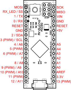
Note that there are INCORRECT versions of this pinout diagram floating around the 'net, due to the original documentation being wrong. This is now corrected, but unfortunately the bad diagram is floating around. The correct one is here.
Right. So now I almost know what I need to do. Point AIN1 to A0 pin to which the IR sensor is connected. Point AIN0 to the INTERNAL_REFERENCE. Set the trigger to change/rise/fall option. Setup an interrupt service routine. Enable the interrupt. Get the other bits in the control registers correct. That's about it.
- The Arduino Micro uses a ATmega32U4 microcontroller.
- The capabilities of the ATmega32U4 are not exactly the same as the microcontroller used on other Arduino boards. Some have more, some have less functionality.
- To make things "easy", programming Arduino is best done using symbolic equates for things - these equates change depending on what board you select in the Arduino IDE. So when pins change between boards, that doesn't matter, you use the same name for things but it compiles into different numbers/bit positions based on the board you choose.
- Lots of online resources don't realise this and use actual bit values when writing to the microcontroller registers. uh oh. So example code won't always work.
- The Arduino Micro isn't exactly a common board, so very few examples for it.
- Pinouts from the ATmega32U4 are not 1:1 with pinouts from the Arduino Micro - you need to find a mapping between the two if you're going to connect something to the Arduino and expect it to get to the correct pin on the ATmega32U4.
- The ATmega32U4 has an onobard analog comparator. This is a quick way of comparing two voltages without having to do an ADC on the voltages. The comparator works with two values - called AIN0 and AIN1 on most of the Arduino microcontrollers - but it seems that this one does not have AIN1; it is handled by some multiplexer which I don't understand yet that lets you select an analog pin as input.
- It is possible to use an internal reference voltage (1.1V, possibly 2.65V - not quite sure - the data sheet pp.55 says 1.1V but elsewhere are claims of 2.65V. Ultimately for my use it doesn't matter which, as both will work as a trigger-point for my IR signal) instead of having to have a second comparison pin in use. This is what I need/want for my project. The internal reference voltage attaches to AIN0.
- Comparators can trigger interrupts. This is the whole point of doing it this way. The trigger for the comparator can be on a change, a fall, or a rise relative to the comparison voltage. Configuration of this is through ATmega32U4 register writes (bit fiddling) with register and bit-names defined with the symbolic equates as mentioned earlier. I need to find the registers and understand all the appropriate bits.
- Comparator Interrupt on the Arduino is "registered" with the ISR(ANALOG_COMP_vect) {} macro. Just put your interrupt code inside the braces. Make it fast - set a flag, and handle the flag in the main loop of the program. Not a rule, just a guideline if you have rapidly triggered interrupts. There are also bits to fiddle to enable the ATmega32U4 to trigger the interrupt.
- The ATmega32U4 pin AIN0 (and whatever the AIN1 equivalent is) are not the same as the Arduino Mega pins A0 and A1. Where you would put an analog input onto A0 and read it (my current configuration does this to let me read the IR sensor values (0-1023)) - instead you need to put the analog input onto the pin(s) used for the comparator. Arduino pins appear to be multiplexed/overloaded so that things aren't immediately clear. There does not seem to be an AIN1 pin, but there is an AIN0 pin which is mapped to PE6 on the ATmega32U4 which according to the schematic is connected to D7 on the Arduino Micro. That's 6th from bottom left on the diagram below. So, that's where I put my analog IR input. Edit: This was a bit of a red herring. The AIN1 can be any analog input on the ATmega32U4, so will use A0 on the Arduino Mega. The AIN0 will be the internal reference voltage.
[*} OK, that's AIN0 - but what about AIN1 which doesn't exist? I want to select an internal reference voltage. There's a comparator library which I couldn't get to work, but a note there says "Atmega32U4: the AIN- of this MCU can be only connected to an analog input pin because the Atmega32U4 doesn't have the AIN1 pin." And how do we "connect to an analog input pin" - we need to specify which one, right? But actually we don't want to do that - we want to connect AIN- to a reference voltage (internal). How? - Per the above doc, "AIN+ can also be connected to the internal voltage reference while AIN- that also be connected to any of the analog input pins" so in fact we DON'T connect AIN0 - we instead point it to internal reference voltage, and we use an analog pin for AIN- (=AIN1 replacement). So, two things to so. 1) tell the ATmega32U4 to use internal reference voltage for/instead of AIN0, and 2) tell the ATmega32U4 to use the analog pin we have our IR signal connected to. Fortunately the library (though it didn't work for me) has given some clues how to do that...
- analogComp Library's README.txt is useful in explaing capabilities and also where in the source code to find stuff
 setOn routine looks like it does the bulk of the work. It says "For the AIN+ you can choose between the following:
AIN0: set the AIN0 pin as input
INTERNAL_REFERENCE: set the internal voltage reference as input
For the AIN- you can choose between the following:
AIN1: set the AIN1 pin as input
A0..Ax: set the Analog Input Channel (max number depends of the MCU)" - So, I want the equivalent of INTERNAL_REFERENCE for AIN+ and I want analog pin A0 for AIN-.
- Here's the source code - analogComp.cpp. The comment "for Atmega32U4, only ADMUX is allowed as input for AIN-" now makes sense to me; there is no AIN1 so we use an analog pin instead. That appears to be controlled through register AC_REGISTER (turn off bit MUX5) and ADMUX (set to analog pin - 0 for A0, 1 or A1...etc). Also, AC_REGISTER |= (1<<ACME); which appears to be setting pin AIN1 - not sure???
- to set INTERNAL_REFERENCE: ACSR |= (1<<ACBG); //set Internal Voltage Reference (1V1)
- There are lots of other bits in ACSR that need to be managed. Some... ADCSRA &= ~(1<<ADEN); ADMUX &= ~31; //reset the first 5 bits (so we can write the analog pin number in). Not sure what ADCSRA bit ADEN does - appear related to ATTINYx313 and not relevant to ATmega32U4.
- Configuring the interrupt based on rising, falling, or change...
// CHANGE...
ACSR &= ~((1<<ACIS1) | (1<<ACIS0)); //interrupt on toggle event (CHANGE), or..
// FALLING...
ACSR &= ~(1<<ACIS0);
ACSR |= (1<<ACIS1); // or...
// RISING...
ACSR |= ((1<<ACIS1) | (1<<ACIS0));
So the register ACSR has bits ACIS0 and ACIS1 controlling the trigger on change/rise/fall.
MODE ACIS1 ACIS0
CHANGE 0 0
FALL 1 0
RISE 1 1
- pin.png (17.83 KiB) Viewed 13555 times
Note that there are INCORRECT versions of this pinout diagram floating around the 'net, due to the original documentation being wrong. This is now corrected, but unfortunately the bad diagram is floating around. The correct one is here.
Right. So now I almost know what I need to do. Point AIN1 to A0 pin to which the IR sensor is connected. Point AIN0 to the INTERNAL_REFERENCE. Set the trigger to change/rise/fall option. Setup an interrupt service routine. Enable the interrupt. Get the other bits in the control registers correct. That's about it.
-
Andrew Davie - "Gomez!", "Oh Morticia."
- Posts: 1590
- Joined: Wed Jan 24, 2007 4:42 pm
- Location: Queensland, Australia
22 posts
• Page 1 of 2 • 1, 2
Return to Andrew Davie's Arduino Televisor
Who is online
Users browsing this forum: No registered users and 2 guests