See for example
Looks like a digital pot controlled via SPI interface is the way to go. The SD card is using the SPI pins, but it seems each device has an "enable" line, so you just daisy-chain them, and select the device you want, and away you go. My first explorations were about the frequency at which the devices can swictch (some around 5us) and the number of different "levels" and I see some with 256 which would be sufficient (per Klaas's statement that 64 would be reasonable). Given frame rate of 12.5Hz, 32 lines and (say) 64 pixels/line that's 25KHz switches. At 5us, that's more than capable. So it seems like I need to go down this route to get current-switched LEDs and abandon the PWM idea.
I hope someone stops me before I get too far along, if I'm wrong!
Narrow-Bandwidth Television Association
Forum for discussion of television and imaging using mechanical, radio, and early electronic systems.
Driving a LED matrix
Moderators: Dave Moll, Andrew Davie, Steve Anderson
63 posts
• Page 3 of 5 • 1, 2, 3, 4, 5
Re: Driving a LED matrix
![]() by Andrew Davie » Fri Mar 17, 2017 11:55 pm
by Andrew Davie » Fri Mar 17, 2017 11:55 pm
-

Andrew Davie - "Gomez!", "Oh Morticia."
- Posts: 1590
- Joined: Wed Jan 24, 2007 4:42 pm
- Location: Queensland, Australia
Re: Driving a LED matrix
![]() by Andrew Davie » Sat Mar 18, 2017 2:00 am
by Andrew Davie » Sat Mar 18, 2017 2:00 am
Here are some observations. Controlling LED brightness via PWM involves the LED being either on, full brightness, or off - black. The proportion of on to off gives perceived brightness. This is fine if the LED isn't moving. However, if you move the LED, then the brain perceives that the LED is on for some period of the travel distance and off for another part. In other words, we no longer see the combined on/off as a brightness, but we see distinct ON and OFF areas. Because in any particular point, the led is either always on or always off.
So this affects NBTV too. Because although the LEDs aren't moving, the position where we see the LED *is*. We have a spinning Nipkow disc in front of the LED array, and as it passes each point in the array the LED is either on, or it is off. For any particular rotation, anyway. So we end up for seeing strips of black, and strips of white. The lengths of those strips depends on the PWM frequency of the LEDs and, of course, the duty cycle at that time. If it's low relative to the speed of the disc rotation, then the strips are quite long. What we ideally want is the PWM frequency to be significantly high such that for any "pixel" position there are many (more than 2) on/off cycles of the PWM so that we "see" a blended on/off. In fact what we're really doing in this situation is shortening the length of the perceived "on" parts and the "off" parts. A combined on+off length is of course one cycle at the frequency of the PWM. That translates directly to a length in terms of the visible area of the Nipkow frame. If we're looking at (say) an image frame that's 4cm high, then that 4cm is scanned 12.5Hz - for 32 lines per scan. So 1/32 of 1/12.5th of a second is the total scan time for the scanline. That's 1/400th of a second to scan the line. Assume (say) 64 "pixels" although we have a very flexible meaning of pixel in a vertical scanline because in fact it's a continuous analog concept rather than a discrete digital concept. But nonetheless, a pixel as defined here is 1/64th of 1/400th of a second long. That's 1/25600th of a second, during which time we want at least two PWM cycles on/off on/off. So we need a frequency of at least 51200Hz to get reasonable speed to a) reduce the visible on/off lines, and b) blend the black/white to greyscale. Even so, 1/2 of 1/64th of a scanline is still a reasonable distance. For 4cm that's 1/2 * 1/64 * 40 mm = 1/3 mm. The eye can see that easily. So it's not going to blend at that resolution - it's just going to look like black and white dots. Which is exactly what I'm seeing.
In the above image, I believe the dark-grey dots are from the previous frame - the camera is not synchronised to the frame rate. But basically these regularly spaced dots that I see are actually the PWM time-based duty cycle visible as distances between on and off pulses of the LEDs. It fits my theory, above.
So the eye can probably easily see detail at 1/50th of a mm. We need at least that. Which means we need probably 30 times smaller separation between on/off states. That's 30 times faster, so now we're looking at 30*25600 Hz = 768kHz. And the Arduino can't really do that - not with a decent duty range, anyway. Well, I should calculate that - I know it can do up to 8MHz with just 0 or 1 for duty. But we need a decent greyscale range - say, 64 or 128 so we need 6 or 7 bits for duty to have appropriate brightness steps. I ballpark-estimate at 2MHz PWM on the LED we'd have sufficient duty bits. Can a LED switch at 2MHz? That's 0.5us per switch, I think. Probably can, but it's pretty quick.
Now that I've written this out, this is similar to what I'm seeing. Rather than greyscale I'm seeing black and white dots separated in space. It's a problem.
In short, to "blend" a PWM driven LED which is behind a spinning disc, you need to account for an effect as if the LED was moving at the speed of the disc hole. That movement separates out the on/off pulses into lines. The PWM frequency needs to be fast enough to fool the brain into having those lines blur together to give the impression of grey instead of black or white. And that requires a mighty fast PWM - faster than I think is practical on the Arduino.
So after having tried and failed for some time to get greyscale pictures or indeed any picture at all at higher speeds, I think that the PWM-driven LED idea might very well be dead. As an experiment, though, I'm going to see if I can put the LED PWM on a separate timer and switch as fast as I possibly can, while keeping enough bits for a decent duty range.
So this affects NBTV too. Because although the LEDs aren't moving, the position where we see the LED *is*. We have a spinning Nipkow disc in front of the LED array, and as it passes each point in the array the LED is either on, or it is off. For any particular rotation, anyway. So we end up for seeing strips of black, and strips of white. The lengths of those strips depends on the PWM frequency of the LEDs and, of course, the duty cycle at that time. If it's low relative to the speed of the disc rotation, then the strips are quite long. What we ideally want is the PWM frequency to be significantly high such that for any "pixel" position there are many (more than 2) on/off cycles of the PWM so that we "see" a blended on/off. In fact what we're really doing in this situation is shortening the length of the perceived "on" parts and the "off" parts. A combined on+off length is of course one cycle at the frequency of the PWM. That translates directly to a length in terms of the visible area of the Nipkow frame. If we're looking at (say) an image frame that's 4cm high, then that 4cm is scanned 12.5Hz - for 32 lines per scan. So 1/32 of 1/12.5th of a second is the total scan time for the scanline. That's 1/400th of a second to scan the line. Assume (say) 64 "pixels" although we have a very flexible meaning of pixel in a vertical scanline because in fact it's a continuous analog concept rather than a discrete digital concept. But nonetheless, a pixel as defined here is 1/64th of 1/400th of a second long. That's 1/25600th of a second, during which time we want at least two PWM cycles on/off on/off. So we need a frequency of at least 51200Hz to get reasonable speed to a) reduce the visible on/off lines, and b) blend the black/white to greyscale. Even so, 1/2 of 1/64th of a scanline is still a reasonable distance. For 4cm that's 1/2 * 1/64 * 40 mm = 1/3 mm. The eye can see that easily. So it's not going to blend at that resolution - it's just going to look like black and white dots. Which is exactly what I'm seeing.
- dotty.jpg (166.82 KiB) Viewed 11623 times
In the above image, I believe the dark-grey dots are from the previous frame - the camera is not synchronised to the frame rate. But basically these regularly spaced dots that I see are actually the PWM time-based duty cycle visible as distances between on and off pulses of the LEDs. It fits my theory, above.
So the eye can probably easily see detail at 1/50th of a mm. We need at least that. Which means we need probably 30 times smaller separation between on/off states. That's 30 times faster, so now we're looking at 30*25600 Hz = 768kHz. And the Arduino can't really do that - not with a decent duty range, anyway. Well, I should calculate that - I know it can do up to 8MHz with just 0 or 1 for duty. But we need a decent greyscale range - say, 64 or 128 so we need 6 or 7 bits for duty to have appropriate brightness steps. I ballpark-estimate at 2MHz PWM on the LED we'd have sufficient duty bits. Can a LED switch at 2MHz? That's 0.5us per switch, I think. Probably can, but it's pretty quick.
Now that I've written this out, this is similar to what I'm seeing. Rather than greyscale I'm seeing black and white dots separated in space. It's a problem.
In short, to "blend" a PWM driven LED which is behind a spinning disc, you need to account for an effect as if the LED was moving at the speed of the disc hole. That movement separates out the on/off pulses into lines. The PWM frequency needs to be fast enough to fool the brain into having those lines blur together to give the impression of grey instead of black or white. And that requires a mighty fast PWM - faster than I think is practical on the Arduino.
So after having tried and failed for some time to get greyscale pictures or indeed any picture at all at higher speeds, I think that the PWM-driven LED idea might very well be dead. As an experiment, though, I'm going to see if I can put the LED PWM on a separate timer and switch as fast as I possibly can, while keeping enough bits for a decent duty range.
-
Andrew Davie - "Gomez!", "Oh Morticia."
- Posts: 1590
- Joined: Wed Jan 24, 2007 4:42 pm
- Location: Queensland, Australia
Re: Driving a LED matrix
![]() by Andrew Davie » Sat Mar 18, 2017 3:20 am
by Andrew Davie » Sat Mar 18, 2017 3:20 am
Calculating the other way around. 16MHz clock. If we assume 7 bits of duty cycle resolution (giving 128 shades) then we divide by 128 to get the period of a complete on/off pulse. Because we need 128 distinct on/off lengths - so the total length of the PWM pulse is 128 clocks. That's 16000000/128 = 125000 Hz. Spread over 12.5 frames and 32 scalines/frame (i.e,. 400 scanlines/second) that's 312.5 PWM cycles/scanilne. With the aforementioned 64 "pixels" that's 4.88 PWM cycles per "pixel". Or to put it another way, each pixel is 4.0cm / 64 = 0.625mm so each PWM cycle would be 0.12 mm long - and that's real easy for the eye to discriminate - we'd see clear black and white dots, not a blended object. More to the point, as single "pixel" would be nearly 5 reasonably distinct black/white bands. Solid black, bright white. So that kind of also says - not gonna work. Really, to get a blend, we have to be blending in the same physical location. A stationary LED. And with the spinning disc, that's effectively like moving the LED as noted earlier. Problem.
-
Andrew Davie - "Gomez!", "Oh Morticia."
- Posts: 1590
- Joined: Wed Jan 24, 2007 4:42 pm
- Location: Queensland, Australia
Re: Driving a LED matrix
![]() by gary » Sat Mar 18, 2017 11:26 am
by gary » Sat Mar 18, 2017 11:26 am
Andrew Davie wrote:Calculating the other way around. 16MHz clock. If we assume 7 bits of duty cycle resolution (giving 128 shades) then we divide by 128 to get the period of a complete on/off pulse. Because we need 128 distinct on/off lengths - so the total length of the PWM pulse is 128 clocks. That's 16000000/128 = 125000 Hz. Spread over 12.5 frames and 32 scalines/frame (i.e,. 400 scanlines/second) that's 312.5 PWM cycles/scanilne. With the aforementioned 64 "pixels" that's 4.88 PWM cycles per "pixel". Or to put it another way, each pixel is 4.0cm / 64 = 0.625mm so each PWM cycle would be 0.12 mm long - and that's real easy for the eye to discriminate - we'd see clear black and white dots, not a blended object. More to the point, as single "pixel" would be nearly 5 reasonably distinct black/white bands. Solid black, bright white. So that kind of also says - not gonna work. Really, to get a blend, we have to be blending in the same physical location. A stationary LED. And with the spinning disc, that's effectively like moving the LED as noted earlier. Problem.
Sorry Andrew, I have people down from Sydney so not much time to follow the last few updates and I may have misinterpreted something.
Your analysis looks pretty correct but is 32.125kHz the limit of your PWM??, I must admit I had been thinking it would be more in the order of my RPi which has PWM of around 18Mhz! I should have read the specs
If it's only capable of 32kHz then obviously your 44.1kHz source is out (without resampling), but theoretically it should still be able to handle the NBTV base frequency of 9.6kHz (theoretically the PWM sampling theorem is the same as the Shannon/Nyquist sampling theorem meaning it has to twice that of the highest frequency you are wanting to reproduce, so in this case a sampling rate of 2 x 9.6kHz = 19.2kHz), but it means you are definitely going to need a filter.
This is an example of the results I was getting with the RPi:
youtu.be/2rrhesQRLes
- gary
Re: Driving a LED matrix
![]() by gary » Sat Mar 18, 2017 1:18 pm
by gary » Sat Mar 18, 2017 1:18 pm
For interest's sake here is how people have added analogue audio to a PI Zero that doesn't have it built in as do the other models.
The recommend the PWM carrier be 10 x the highest signal frequency (sounds right), which makes it 96kHz for our application.
They have the luxury of 50 Mhz PWM.
The recommend the PWM carrier be 10 x the highest signal frequency (sounds right), which makes it 96kHz for our application.
They have the luxury of 50 Mhz PWM.
- gary
Re: Driving a LED matrix
![]() by Andrew Davie » Sat Mar 18, 2017 1:43 pm
by Andrew Davie » Sat Mar 18, 2017 1:43 pm
gary wrote:For interest's sake here is how people have added analogue audio to a PI Zero that doesn't have it built in as do the other models.
The recommend the PWM carrier be 10 x the highest signal frequency (sounds right), which makes it 96kHz for our application.
They have the luxury of 50 Mhz PWM.
I'll give it a go at the highest frequency I can manage and report back. In the meantime I have purchased a few digital potentiometer chips to play with, as it will be good to learn how to use those with the Arduino anyway. And if I get those working, then the LEDs are going to stay lit and there won't be any artefacting/interaction between the PWM and the disc rotation.
-
Andrew Davie - "Gomez!", "Oh Morticia."
- Posts: 1590
- Joined: Wed Jan 24, 2007 4:42 pm
- Location: Queensland, Australia
Re: Driving a LED matrix
![]() by Andrew Davie » Sat Mar 18, 2017 2:15 pm
by Andrew Davie » Sat Mar 18, 2017 2:15 pm
I've bought myself a few 4151-103E/P digital potentiometers to play with. Now I need to understand how to efficiently use this with an array of LEDs. It seems there's already a library for controlling the MCP4XXX range of SPI controlled digital potentiometers.
-
Andrew Davie - "Gomez!", "Oh Morticia."
- Posts: 1590
- Joined: Wed Jan 24, 2007 4:42 pm
- Location: Queensland, Australia
Re: Driving a LED matrix
![]() by Andrew Davie » Sat Mar 18, 2017 4:42 pm
by Andrew Davie » Sat Mar 18, 2017 4:42 pm
OK, ran out and got myself some MCP4151-103E/P chips and wired one up to an Arduino Micro. It's running a small loop to toggle the 4151 through 256 values and, of course, the LED follows suit. I will now review how this works with a higher voltage (22V) and my LED matrix - I just have to think about it a bit first.
The goal is to replace the PWM LED driver board with a new 4151 board that drives the LED array via current changes.
The goal is to replace the PWM LED driver board with a new 4151 board that drives the LED array via current changes.
- Attachments
-
 VID_20170318_161309.mp4
- (871.96 KiB) Downloaded 501 times
-
Andrew Davie - "Gomez!", "Oh Morticia."
- Posts: 1590
- Joined: Wed Jan 24, 2007 4:42 pm
- Location: Queensland, Australia
Re: Driving a LED matrix
![]() by Andrew Davie » Sat Mar 18, 2017 5:25 pm
by Andrew Davie » Sat Mar 18, 2017 5:25 pm
Looking for some hints on how to proceed. Now that I have the MCP4151, it can happily handle 25 mA to a LED which is running off the 5V Arduino supply. But what I want to do is connect my LED array running instead of a 22V input separate to the Arduino. The 4151 remains powered from the Arduino, but the LED array is powered from the 22V. Is it safe to simply share the ground between the Arduino and the 22V GND, the 22V V+ to the LED array, and connect the output of the 4151 to a resistor to the LED array GND?
-
Andrew Davie - "Gomez!", "Oh Morticia."
- Posts: 1590
- Joined: Wed Jan 24, 2007 4:42 pm
- Location: Queensland, Australia
Re: Driving a LED matrix
![]() by gary » Sat Mar 18, 2017 7:16 pm
by gary » Sat Mar 18, 2017 7:16 pm
Andrew Davie wrote:Looking for some hints on how to proceed. Now that I have the MCP4151, it can happily handle 25 mA to a LED which is running off the 5V Arduino supply. But what I want to do is connect my LED array running instead of a 22V input separate to the Arduino. The 4151 remains powered from the Arduino, but the LED array is powered from the 22V. Is it safe to simply share the ground between the Arduino and the 22V GND, the 22V V+ to the LED array, and connect the output of the 4151 to a resistor to the LED array GND?
Well no, I wouldn't think so, It's ok to tie the grounds together, however, and I am not familiar with this device, but the spec says the outputs can only sink 25 mA, your previous calculations indicated you have 200 mA down to ground. In fact if I follow what you are wanting to do with this you would be running it in rheostat mode and the current is limited to a paltry 1mA.
If I am not greatly mistaken you would need to buffer it in some way, possibly with the existing circuitry (i.e. you control the base current with this device).
It might be time to rough up a schematic so we can be sure of what you are trying to do. Words are great but they can be misinterpreted if you know what I mean.
BTW Andrew a few posts ago I embedded a youtube video into a post, that doesn't seem to be working now, does it look OK to you? I may have broken my browser with some configuration changes.
- gary
Re: Driving a LED matrix
![]() by Andrew Davie » Sat Mar 18, 2017 8:40 pm
by Andrew Davie » Sat Mar 18, 2017 8:40 pm
This is my current thinking. Using a TIP31 transistor to feed the 200mA of the LED array. It has a gain of 25x if I have interpreted the data sheet correctly. That would require a base current of 8mA, so there is 208mA going to ground through the emitter. The voltage drop across the TIP31 is about 0.6V for that current (200mA). Ignore the "unkown" drop in the diagram; I was thinking of a drop to an Arduino I/O pin but in fact we just deal with the 25mA maximum current at the MCP4151. So the voltage at the emitter is 4.4V and 208mA so that's a resistor (at the emitter out) of 21.2 ohms or thereabouts. Say, 20. Cacluating backwards... that's 220 mA total, or 20mA at base of TIP31, which is fine.
Edit: Do not even attempt to construct the below circuit. It is disasterous! The LED matrix will just bypass everything and blow up. Look here for a revised version.
I am quite out of my depth, to be honest. But if I have it correct, then the current on the MCP4151 pin will be 20mA maximum (with 20 ohm resistor, not the 16 in the diagram).
In operation, the Arduino is powering the MCP4151 with 5V from its output pin, and using SPI pins to communicate with the MCP4151 (digitial potentiometer). It sends a value from 0 to 255 on the SIP output. The MCP4151 adjusts its output resistance accordingly, so we have a variable resistance at the base of the TIP31 transistor (which has a gain of 25x I hope). The MCP4151 is a 10k ohm device with 8-bit resolution. So, mmh, now I see what I'm doing here. If we have the maximum resistance 10k at the base of TIP31, with 5V, then current is negligible, nothing goes to the LED matrix. Since we are supplying the TIP31 from the Arduino 5V, we need to limit the current on that supply to something less than 50mA (I'm guessing here - its 20mA on the I/O pins, but 50mA on the 3.3V output. So assuming the 5V output is the same current max as the 3.3V). Assume the MCP4151 puts 5V on the output so 5.0-0.6 = 4.3V at a maximum of 25mA the question is: with the MCP4151 at lowest resistance (say, 0 ohms) then should I protect it according to its maximum current? If I put a resistor of 180 ohms (ignore the 100 ohm on the diagram) then that would protect the MCP4151 pin from excessive current at 4.4V (just!). And that would presumably indirectly protect the Arduino 5V pin too which in any case has a presumed higher current capacity (50mA).
I get the feeling I'm not "getting it", but sharing my thinking here hoping for corrections
Edit: Do not even attempt to construct the below circuit. It is disasterous! The LED matrix will just bypass everything and blow up. Look here for a revised version.
- mcp4151rev3.jpg (174.38 KiB) Viewed 11586 times
I am quite out of my depth, to be honest. But if I have it correct, then the current on the MCP4151 pin will be 20mA maximum (with 20 ohm resistor, not the 16 in the diagram).
In operation, the Arduino is powering the MCP4151 with 5V from its output pin, and using SPI pins to communicate with the MCP4151 (digitial potentiometer). It sends a value from 0 to 255 on the SIP output. The MCP4151 adjusts its output resistance accordingly, so we have a variable resistance at the base of the TIP31 transistor (which has a gain of 25x I hope). The MCP4151 is a 10k ohm device with 8-bit resolution. So, mmh, now I see what I'm doing here. If we have the maximum resistance 10k at the base of TIP31, with 5V, then current is negligible, nothing goes to the LED matrix. Since we are supplying the TIP31 from the Arduino 5V, we need to limit the current on that supply to something less than 50mA (I'm guessing here - its 20mA on the I/O pins, but 50mA on the 3.3V output. So assuming the 5V output is the same current max as the 3.3V). Assume the MCP4151 puts 5V on the output so 5.0-0.6 = 4.3V at a maximum of 25mA the question is: with the MCP4151 at lowest resistance (say, 0 ohms) then should I protect it according to its maximum current? If I put a resistor of 180 ohms (ignore the 100 ohm on the diagram) then that would protect the MCP4151 pin from excessive current at 4.4V (just!). And that would presumably indirectly protect the Arduino 5V pin too which in any case has a presumed higher current capacity (50mA).
I get the feeling I'm not "getting it", but sharing my thinking here hoping for corrections
-
Andrew Davie - "Gomez!", "Oh Morticia."
- Posts: 1590
- Joined: Wed Jan 24, 2007 4:42 pm
- Location: Queensland, Australia
Re: Driving a LED matrix
![]() by Andrew Davie » Sat Mar 18, 2017 8:45 pm
by Andrew Davie » Sat Mar 18, 2017 8:45 pm
gary wrote:BTW Andrew a few posts ago I embedded a youtube video into a post, that doesn't seem to be working now, does it look OK to you? I may have broken my browser with some configuration changes.
I had exactly the same problem yesterday. I think it's a YouTube issue. I spent some time trying to fix my browser settings, clearing the cache, etc., and gave up. And then it just came good and started working again. So given it's happened to us both, I think it's not your configuration at fault. Give it a short while and see if it comes good.
Your video is displaying fine for me.
-
Andrew Davie - "Gomez!", "Oh Morticia."
- Posts: 1590
- Joined: Wed Jan 24, 2007 4:42 pm
- Location: Queensland, Australia
Re: Driving a LED matrix
![]() by gary » Sat Mar 18, 2017 9:51 pm
by gary » Sat Mar 18, 2017 9:51 pm
Andrew can you show me how you hooked it up in the one LED demo above please?
- gary
Re: Driving a LED matrix
![]() by Andrew Davie » Sat Mar 18, 2017 11:42 pm
by Andrew Davie » Sat Mar 18, 2017 11:42 pm
gary wrote:Andrew can you show me how you hooked it up in the one LED demo above please?
Essentially like in this diagram...
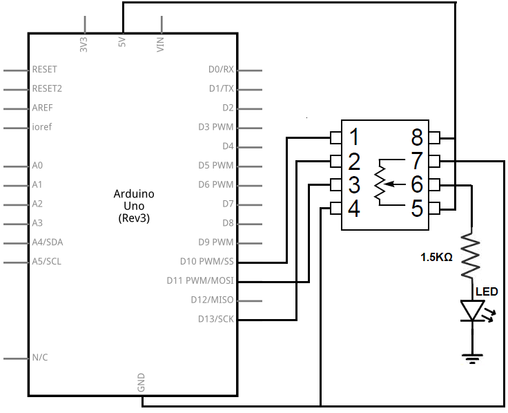
from: How to Build a Digital Potentiometer Circuit Using a MCP4131 - yes, a different chip, but the pinouts are the same in terms of name/function so I connected likewise. The Arduino pins I chose were different because the Arduino micro has dedicated pins, and they are different to the Ardino Uno shown here. So I selected D10 for the CS the same, but the actual dedicated SCK, MOSI pins for the Arduino side I used instead of as per the diagram.
Mapping:
MCP4151 --> Arduino
1 --> D10 (chip select)
2 --> SCK
3 --> MOSI
4 --> GND
5 --> 5V (same as 8 )
6 --> LED
7 --> GND
8 --> 5V (same as 5 )
-
Andrew Davie - "Gomez!", "Oh Morticia."
- Posts: 1590
- Joined: Wed Jan 24, 2007 4:42 pm
- Location: Queensland, Australia
Re: Driving a LED matrix
![]() by Andrew Davie » Sun Mar 19, 2017 12:42 am
by Andrew Davie » Sun Mar 19, 2017 12:42 am
Here's a revised version with everything as I currently understand it.
Edit: Do not even attempt to construct the below circuit. It is disasterous! The LED matrix will just bypass everything and blow up. Look here for a revised version.
Edit: Do not even attempt to construct the below circuit. It is disasterous! The LED matrix will just bypass everything and blow up. Look here for a revised version.
- mcp4151rev4.jpg (172.26 KiB) Viewed 11586 times
-
Andrew Davie - "Gomez!", "Oh Morticia."
- Posts: 1590
- Joined: Wed Jan 24, 2007 4:42 pm
- Location: Queensland, Australia
63 posts
• Page 3 of 5 • 1, 2, 3, 4, 5
Return to Andrew Davie's Arduino Televisor
Who is online
Users browsing this forum: No registered users and 2 guests